In general, the creation and demonstration of network topology using simulator is considered as the possible process. Now, we have described the keynotes about network topology.
Significance of Network Topology
The network topology is considered as the physical and logical arrangement of connections and nodes. Modules in topology used to provide the functions such as,
- Virtual network segments are used to confine and test sensitive portions of network
- Testing is used to protect the resources and the reduction of risk
- Attacks are simulated against virtual networks
- Virtual topologies are created to test the network changes
Creation of Network Topology Using Simulator
Following that, our experts have showcased the creation process of network topology through the utilization of following code based on OMNeT++ which is the network simulator used in this process.
package flora.simulations;
………………
network Solid_Waste_Management_NW
{
parameters:
int numberOfNodes = default(50); int numberOfGateways = default(2);
int networkSizeX = default(1000); int networkSizeY = default(1000);
@display(“bgb=1000,1000”);
submodules:
IoT1: LoRaNode { @display(“p=108.864006,38.304;i=device/IoT”); }
loRaGW[numberOfGateways]: LoRaGW { @display(“p=157,238;is=s”); }
LoRaMedium: LoRaMedium { @display(“p=1,1;is=vs”); }
networkServer: StandardHost {
parameters:
@display(“p=523.15204,153.216;i=device/server”);
}
configurator: Ipv4NetworkConfigurator {
parameters:
assignDisjunctSubnetAddresses = false;
@display(“p=1,1;is=vs”);
}
internetCloud: InternetCloud { @display(“p=418.32,59.472”); }
IoT2: LoRaNode { @display(“p=53.424,59.472;”); }
IoT3: LoRaNode { @display(“p=78.624,129.024”); }
IoT4: LoRaNode { @display(“p=38.304,129.024”); }
IoT5: LoRaNode { @display(“p=108.864006,89.712006”); }
…………
gwRouter[numberOfGateways]: Router { @display(“p=497.95203,356.752”); }
nsRouter: Router { @display(“p=528.192,68.544”); }
connections:
networkServer.ethg++ <–> Eth1G <–> nsRouter.ethg++;
nsRouter.pppg++ <–> Eth1G <–> internetCloud.pppg++;
for i=0..numberOfGateways-1 {
networkServer.pppg++ <–> Eth1G <–> gwRouter[i].pppg++;
gwRouter[i].ethg++ <–> Eth1G <–> loRaGW[i].ethg++;
}
}
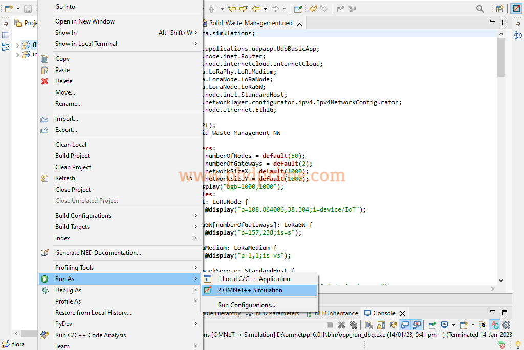
Demonstration of Network Topology Using Simulator
Consequently, we have implemented the network topology using the OMNeT++ simulator through right clicking the project name and choosing the Run as option to OMNeT++ simulation.
Finally, the result is acquired through the implementation of network topology is highlighted in the following.

To this end, we are always ready to give suggestion on the stage where you face some difficulties with the required assistance for your research.


